Copyright © Shenzhen Disperse Equipment Co., Ltd. All Rights Reserved. Site Map
- +86-13824381687
- 821742327@qq.com
- Room 302, Building D, Tangqian Zhongzhi Creative Park, Zhangge Community, Fucheng Street, Longhua District, Shenzhen City


In the industrial production of lithium batteries, die extrusion coating has become the most widely used coating method due to its advantages such as high precision, wide coating window, and high reliability. As shown in Figure 1, the slurry is provided by a precise feeding system (such as a screw pump), enters the internal cavity of the die, and is evenly distributed in the direction of the coating width. Finally, the slurry is squeezed through the slit of the die and moves coating on the substrate. Due to the fluid characteristics of the slurry, half-moon features as shown in Figure 1 are easily formed at the starting and ending points of the coating and on both sides of the edges. During the coating process, the sudden increase in thickness at the edge of the pole piece is called the "thick edge" phenomenon.

Figure 1 Schematic diagram of extrusion coating
According to the structural design of the battery and the corresponding process design, the coating process of lithium battery electrodes can be divided into continuous coating and intermittent coating. As shown in Figure 2, in continuous coating, the thick edge has an impact on battery performance and process. The problem is mainly at the edges on both sides of the coating. For gap coating, in addition to the edges on both sides, this thick edge may also exist at the starting and ending edges (head and tail) of the coating. This thick edge phenomenon is undesirable and can cause problems for the cell process and cell performance and consistency.

Figure 2 Structural diagram of continuous coating and intermittent coating methods
The dangers of thick edges
Whether it is continuous coating or intermittent coating (as shown in Figure 2), this half-moon morphology will seriously affect the uniformity of the coating. Generally, the edge thickness of the coating is several to more than ten microns thicker than the normal area. When the coating is dried and rolled up, hundreds or thousands of layers of pole pieces are rolled into one roll, and the convex lines on the side edge of the coating accumulate to several millimeters. , causing the pole roll to bulge, and in severe cases, the pole piece will break, which seriously affects the uniformity of coating and winding and its subsequent processes.
This thick edge will also affect the rolling process of the pole piece. Since the edge thickness is several microns or more than ten microns larger than the middle part, when the rolling roller pressure acts on the pole piece, the area with large edge thickness will bear greater rolling force. force, resulting in inconsistent lateral densities of roller compaction of pole pieces. On the one hand, this will cause greater warpage of the pole pieces after rolling to form serpentine pole pieces. In subsequent processes such as slitting, die-cutting, and winding, In the process, the tension distribution of the pole pieces is uneven, and the alignment of the pole piece rewinding and unwinding cannot be guaranteed. This will also affect the processing size of the pole pieces, and defective products are prone to occur.
The uneven thickness and compaction density of the pole pieces caused by the thick edge phenomenon also have an impact on battery performance. During the charge and discharge process, uneven current distribution may occur, making polarization more likely to occur. Therefore, the battery pole pieces receive inconsistent forces during the expansion and contraction process of charging and discharging, and thick edges are more likely to fail.
Generally, during 3C battery process design, the edges of the pole pieces are cut off to eliminate the adverse effects of this thick edge. While power batteries require high power and energy, battery design often requires retaining the edges of the coating. Therefore, the thick edge phenomenon has attracted more attention. Marcel Schmitt and others studied the impact of coating process parameters on the thick edges on both sides of continuous coating. Expect to understand and recognize the reasons why this happens.
Quantitative description of the thick edge phenomenon
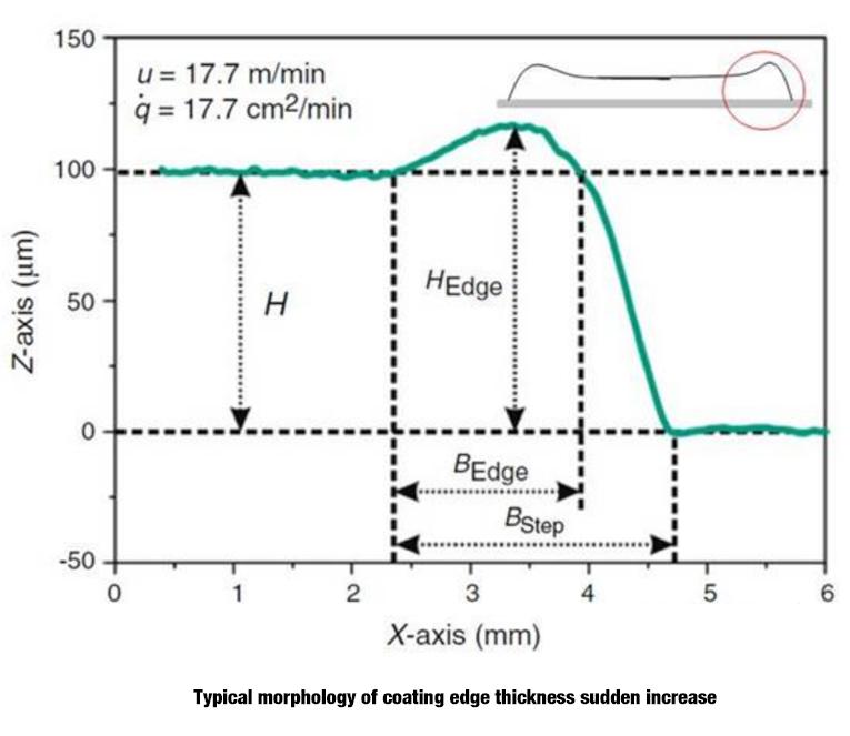
Figure 3 Typical morphology of sudden increase in coating edge thickness
In order to analyze the edge effect of the coating, the author introduces some characteristic parameters to quantitatively characterize the thick edge phenomenon of the coating. As shown in Figure 3, this is a typical morphology of the sudden increase in thickness at the edge of the coating. The middle thickness of the coating is H (H=100μm in Figure 3), and the thickness of the convex point of the coating is HEdge. The dimensionless thickness H* is defined is formula (1):
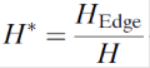
Ideally, H* is equal to 1, and there is no thick edge at the edge of the pole piece coating.
Equation (2) defines the dimensionless width of the thick edge of the coating:
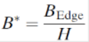
Among them, B* is the dimensionless width of the thick edge, BEdge is the thickness of the convex coating width, measure the thickness of the coating, and the position when the thickness value is first detected as 105% of H is defined as the starting point of BEdge, continue The position when the transverse measurement thickness changes to H is defined as the end point of BEdge. As shown in Figure 3, H* can even reach more than 10 in general lithium battery coating. The gradient R* of the thick edge coating is defined as formula (3):

Among them, the end position of BStep is the position where the thickness of the pole piece detected for the first time is 105% of the thickness of the current collector.
The above three dimensionless parameters are used to quantitatively describe the thickness, width and gradient characteristics of the thick edge of the pole piece coating.
Factors affecting the thick edge phenomenon
There are several main factors that affect the thick edge phenomenon of pole piece coating: (1) The geometric characteristics of the coating die and the coating process parameters. The schematic diagram of the die extrusion coating flow field is shown in Figure 4. The die Geometric parameters and coating process parameters include slit size S, die outlet slurry flow rate q, die and coating roller gap size G, coating speed U, coating wet thickness H, etc.; (2) Properties of the slurry, Especially the surface tension of the slurry.
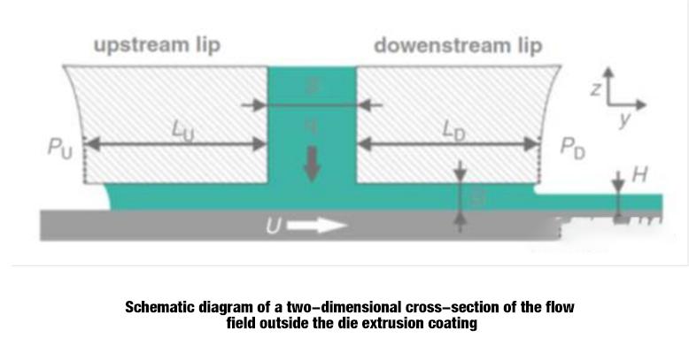
Figure 4 Schematic diagram of a two-dimensional cross-section of the flow field outside the die extrusion coating
(1) Influence of coating speed
Marcel Schmitt et al.’s experimental study on the coating process of lithium-ion battery anode slurry found that the coating speed has almost no effect on the dimensionless thickness and width of the thick edge, but will affect the gradient characteristic R* of the thick edge. When the coating speed increases , R* increases accordingly, that is, the thick edge thickness changes more sharply, as shown in Figure 5.
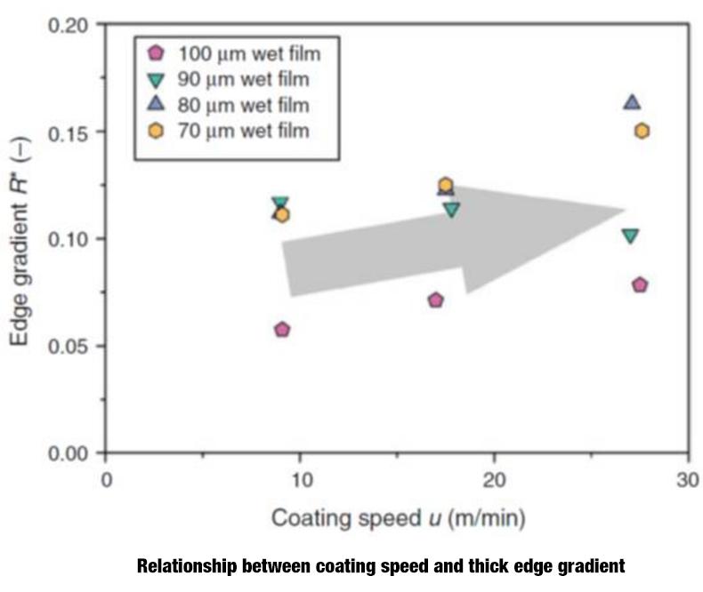
Figure 5 Relationship between coating speed and thick edge gradient
(2) Influence of coating gap
In 1986, Dobroth et al. summarized the empirical formula (4) for thick edge coating thickness and coating process:
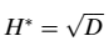
Among them, D is the slurry drag force ratio, which is defined as the ratio of the coating speed U and the average speed of the slurry at the outlet USlurry. It can be calculated by formula (5):

In the formula, q is the slurry volume flow rate, H is the wet thickness of the coating, and G is the coating gap. Therefore, the thick edge coating thickness is related to the dimensionless coating gap G*.
Figure 6 shows the experimental data diagram and formula prediction relationship between the dimensionless coating gap G* and the dimensionless thickness of the thick edge H*. According to the empirical formula, when the coating gap increases, the thickness of the thick edge increases accordingly, but the correlation is seen from the experimental data. Not particularly big. As the coating gap increases, the width of the thick edge coating increases, as shown in Figure 7. Therefore, reducing the coating gap is an effective measure to suppress the thick edge phenomenon.
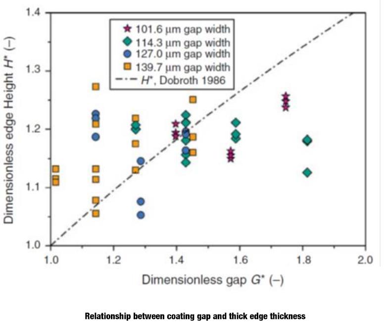 Figure 6 Relationship between coating gap and thick edge thickness

Figure 7 Relationship between coating gap and thick edge width
(3) Effect of surface tension
In addition, the properties of the slurry also have a huge impact on the thick edge. On the one hand, when extruded from the die, the viscoelastic slurry fluid will expand. Due to the additional stress on the edge wall of the die, the slurry expansion effect at the edge will occur. more obvious, resulting in thick edges. In addition, under the surface tension of the slurry, the coating will be cast during the drying process, which will also cause thick edges. As shown in Figure 8, when the coating is dried, the drying speed is the same everywhere, but the solvent evaporates faster at the edge, so when the edge components change faster, if there are no additives such as surfactants in the slurry, or the dispersed particles are suspended When the surface tension of the liquid is greater than the surface tension of the solvent, the slurry flows toward the edge, eventually leading to the thick edge phenomenon.
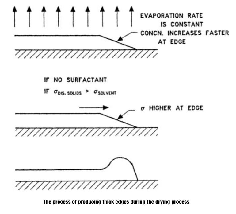
Figure 8 The generation process of thick edge phenomenon during drying process
Solutions to the thick edge phenomenon
The coating thick edge phenomenon is an unfavorable defect. Based on the above experimental results and analysis, the measures to prevent and alleviate the thick edge phenomenon are:
(1) When the slurry flow rate is constant, reducing the slit size can increase the exit velocity of the slurry at the die, thereby reducing the drag force ratio D of the slurry, thereby reducing the dimensionless thickness H* of the thick edge coating, but When the slit size becomes smaller, the pressure inside the die is greater, which is more likely to cause the die exit shape to expand, resulting in uneven lateral thickness of the coating, which requires higher-precision coating equipment.
(2) Reducing the coating gap G can limit the thickness and width of the thick edge coating.
(3) Reduce the surface tension of the slurry, such as adding surfactants, reducing viscosity, etc., to inhibit the slurry from spreading to the edge during the drying process.
(4) Optimize the exit shape of the slit gasket, change the direction and size of the slurry flow velocity, reduce the stress state of the edge slurry, and weaken the edge expansion effect of the slurry.